
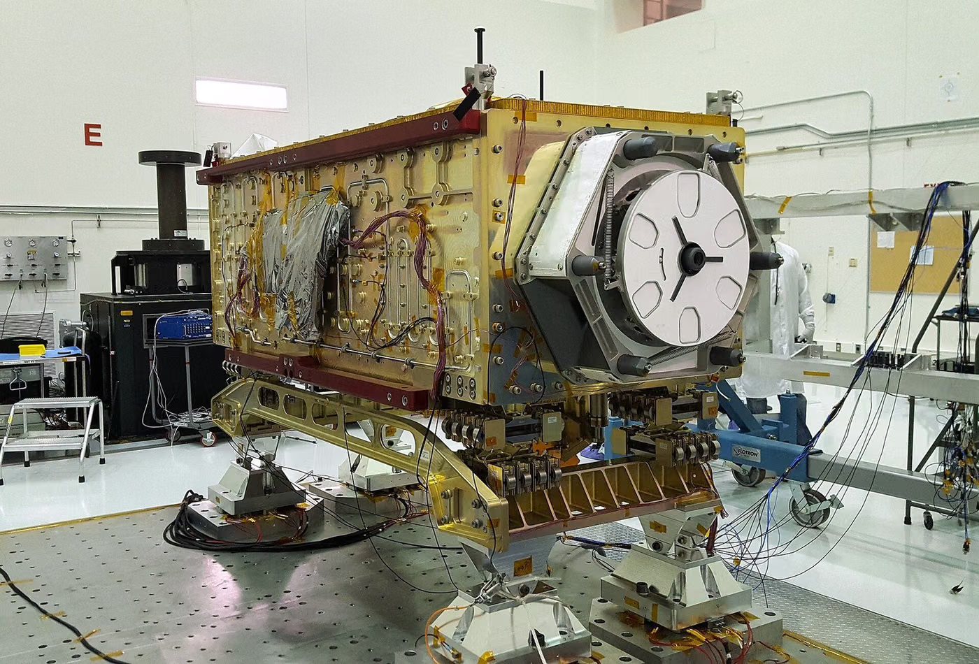
What Is Bump?
The bump test is one in which low-amplitude pulses, repeated thousands of times, are applied to the sample. It is defined in IEC 60068-2-29 and represents continuous jolting during transport.
Purpose of Bump
The purpose is to verify that repeated pulses do not cause loosening or fatigue in fasteners.
Which Products Is Bump Applied To?
- Electronic units
- Railway and automotive equipment
- Portable devices
- Packaged products
In Which Sectors Is Bump Used?
Standards Related to Bump
- IEC 60068-2-29series of environmental testing methods test
- IEC 61373vibration and shock in railway vehicle equipment test
- IEC 60068series of environmental testing methods test
- MIL-STD-810environmental engineering assessments and laboratory tests test
- RTCA DO-160Environmental conditions and test methods in aviation equipment test
- SAEautomotive and aerospace engineering standards test
- ISO 16750Environmental conditions in vehicle electrical/electronic equipment test
- UN 38.3Transport safety tests on lithium batteries test
Bump Conditions
- Tepe ivme
- Defined in the specification; typically 10 – 100 g
- Pulse duration
- Defined in standard (ms)
- Number of shocks
- High; typically 1000 – 4000 pulses
- Axis
- Axes(ies) defined in the specification
Equipment for Bump
- Bump test machine
- Accelerometer and counter
- Mounting fixture
- Function monitoring
Sample Requirements for Bump
- The fixture must be rigid
- Fastener torque values must be recorded
- Function must be checked before the test
Duration of Bump
Depends on the number of pulses; typically several hours to one working day.
Bump Procedure
- 1Pulse amplitude and duration are set.
- 2The sample is mounted on the fixture.
- 3The defined number of pulses is applied.
- 4Loosening and function are examined at interim checks.
- 5A final function check and visual inspection are performed.
Bump Acceptance Criteria
The acceptance criterion is defined in the specification: no loosening of fasteners, no cracking, and continuity of function.
Evaluation of Results
Loss of fastener torque and cracking in solder joints are assessed.
Bump Report
- Standard applied
- Peak acceleration, pulse duration and count
- Axis information
- Loosening and functional results
Accreditation
EUROLAB holds internationally recognised accreditation obtained from accreditation bodies party to the IAF and ILAC multilateral recognition arrangements, under ISO/IEC 17025 for laboratory testing, ISO/IEC 17020 for inspection and surveillance, and ISO/IEC 17021-1 and ISO/IEC 17065 for system and product certification. This chain ensures the reports and certificates issued are accepted worldwide.
Whether this test can be offered within accredited scope depends on your product and the standard applied; since accreditation is method-based, the scope is confirmed in writing at the quotation stage.
Scope and authorisationsRelated Regulations
- Rail and automotive equipment specifications
Vibration and Shock — What Does This Testing Field Cover?
The section below describes the field that the Bump test belongs to; the conditions and acceptance criteria of this particular test are given in the sections above. The scope specific to your product is confirmed in writing at the quotation stage.
Vibration and shock testing shows whether a product withstands mechanical dynamic loads. The two phenomena are distinct: vibration is a continuous and repeated loading, while shock is a single instantaneous impact at high acceleration. They produce different failure modes and are required separately.
The failure produced by vibration is FATIGUE: a solder joint cracks, a cable sheath abrades, a screw loosens, a connector loses contact. The failure produced by shock is FRACTURE: a brittle component shatters, a bracket breaks, a board comes out of its holder. Testing a product under vibration therefore does not show that it also withstands shock.
Vibration is applied in three forms, each giving different information. Sine vibration sweeps at a single frequency; it is used to find the resonant frequencies of the product and is very valuable at the design stage. Random vibration represents the broadband nature of the real environment and is preferred as evidence of durability. Sine-on-random and random-on-random profiles simulate together the broadband noise superimposed on dominant frequencies from engines and rotors — this is necessary in helicopter and turboprop applications.
RESONANCE is the concept at the centre of the field. Every structure has its own natural frequencies; as the excitation frequency approaches one of them the amplitude grows and the product is exposed to an acceleration many times the input level. A resonance search is therefore carried out before the test, and a design change often takes the form of shifting the resonance rather than lowering the level.
In this family the FIXTURE is part of the result, and this is the most frequently overlooked point. How the specimen is attached to the shaker directly changes the energy transmitted and the resonance behaviour. A poorly designed fixture brings its own resonances into play and imposes a load the product would not otherwise see, or conversely damps the real load and protects the product. Results obtained with different fixtures cannot be compared.
The choice of measurement point also determines the result. The control accelerometer is placed on the fixture and monitoring accelerometers at critical points of the product; the report must document these positions. Accelerations measured at different points in the same test can differ markedly.
Profiles are divided by application area: transport vibration (packaging and shipping), vehicle vibration (by mounting location), rail (EN 61373 categories), aviation (DO-160 sections), military (MIL-STD-810 methods) and battery transport (UN 38.3 T3). The same product passes through different profiles under different programmes.
Method groups in this field
Sine vibration
Determining resonances by frequency sweep and withstand at defined frequencies; the most informative test at the design stage.
Random vibration
Durability with a broadband power spectral density profile; the approach that best represents the real environment.
Combined profiles
Sine-on-random and random-on-random; for dominant frequencies arising from rotating machinery.
Classical shock
Defined acceleration and duration with half-sine, sawtooth and trapezoidal pulse shapes.
Free fall and toppling
Realistic drop scenarios arising from handling; decisive for portable products.
Resonance search and monitoring
Detection of structural change (cracking, loosening) by sweeps before and after the test.
Commonly confused in this field
- Shock and vibration are not the same test; one produces fracture and the other fatigue, and they are required separately.
- A report that does not document the fixture cannot be compared; a fixture can bring its own resonance into play.
- Levels come from the product standard or the programme specification; the standard does not define a single universal level.
- Without a resonance sweep before and after the test, structural damage can go unnoticed; the product may appear to work while being cracked internally.
- The position of the measurement point must be reported; accelerations measured at different points in the same test differ markedly.
- If the product is not operated during the test, intermittent loss of contact remains invisible.
Which decisions these results support
- Verification of transport and in-use durability
- Transport and vehicle vibration conformity for batteries
- Rail, aviation and defence qualification files
- Root cause analysis of solder, connector and joint failures
- The decision to shift a resonance through a design change
Related Tests


Frequently Asked Questions About Bump
According to which standard is Bump made?
Bump is executed in scope IEC 60068-2-29 and IEC 61373. The limit values and acceptance criteria to be applied are defined in the product standard; The version valid for your product is confirmed in writing at the offer stage.
Which products does Bump apply to?
Mainly applied to Electronic units, Railway and automotive equipment, Portable devices and Packaged products. Whether your product is included in the scope is determined by examining its technical specifications and intended use.
Under what conditions is Bump done?
The determining parameters are: Tepe ivme — Defined in the specification; typically 10 – 100 g, Pulse duration — Defined in standard (ms) and Number of shocks — High; typically 1000 – 4000 pulses. The full terms are in the "Test Conditions" section on the page and vary depending on the product standard.
What kind of sample is needed for Bump?
The fixture must be rigid, Fastener torque values must be recorded and Function must be checked before the test. The number of samples is determined according to the product standard and the scope to be reported.
How long does Bump take?
Depends on the number of pulses; typically several hours to one working day. This duration belongs to the experiment itself; sample preparation, queuing and reporting are also evaluated. A realistic schedule for your product is given in the offer.
What is the Bump result called "appropriate"?
The acceptance criterion is defined in the specification: no loosening of fasteners, no cracking, and continuity of function.