
What Is UNECE R10?
UNECE R10 is the regulation that regulates the electromagnetic compatibility type approval of vehicles and vehicle components. It covers radiated emission and immunity at the vehicle level and relevant CISPR and ISO tests at the component level.
Purpose of UNECE R10
The aim is to obtain type approval by certifying that the vehicle and its electronic components do not emit interference to their surroundings and operate safely under external electromagnetic fields.
Which Products Is UNECE R10 Applied To?
- Passenger and commercial vehicles
- Electronic control units (ECUs)
- Electric vehicle charging systems
- Lighting and display systems
- Electric drive components
In Which Sectors Is UNECE R10 Used?
Standards Related to UNECE R10
- UNECE R10electromagnetic compatibility in vehicles test
- CISPR 12radio interference from vehicles test
- CISPR 25Radio degradation of in-car components test
- ISO 11452 series
- The ISO 7637 series
UNECE R10 Conditions
- Vehicle level emissions
- Broadband and narrowband radiated emission; CISPR 12 based
- Vehicle level immunity
- Field strength is applied in the defined frequency band
- Component level
- CISPR 25 emission and ISO 11452 immunity tests
- Charging mode
- In electric vehicles, charging emissions and immunity are evaluated separately
Equipment for UNECE R10
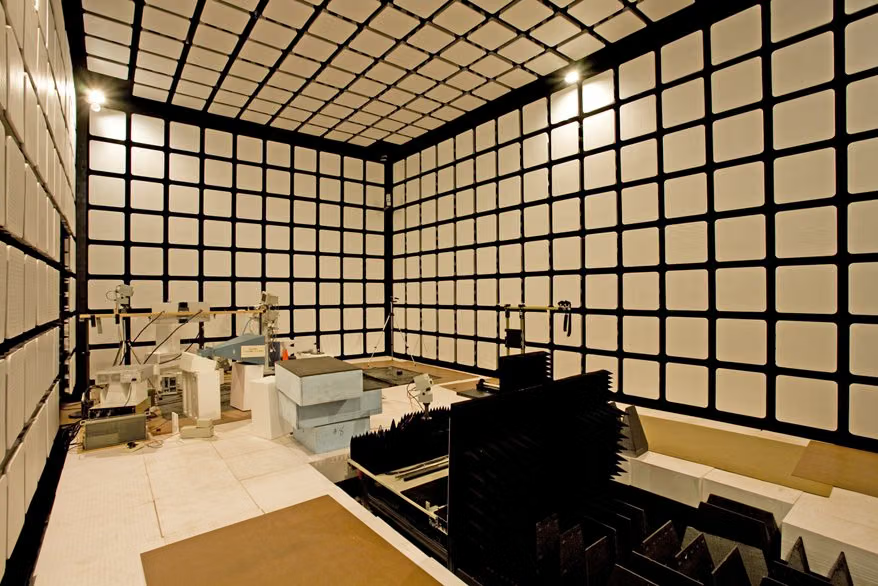
- Vehicle-sized anechoic chamber and turntable
- Antennas and power amplifiers
- EMI receiver
- Dynamometer (for vehicle loading)
- Component level CISPR 25 test pattern
Sample Requirements for UNECE R10
- The vehicle or component must represent mass production
- The operating modes and charging scenarios to be tested must be determined.
- Wiring harness layout must represent actual vehicle
- Function monitoring points must be defined
Duration of UNECE R10
It depends on the scope. Component level programming can take days, full vehicle approval can take weeks.
UNECE R10 Procedure
- 1The scope of approval (vehicle or component) and the list of tests to be applied are determined.
- 2The sample is installed in the test rig and operating modes are defined.
- 3Emission measurements are taken and compared with the limits.
- 4Immunity tests are applied at the defined levels.
- 5Experiments are conducted on electric vehicles in charging mode.
- 6The results are compiled into the type approval file.
UNECE R10 Acceptance Criteria
Acceptance criteria are defined in UNECE R10: emission limits are not exceeded and safety-related functions are not impaired during immunity tests.
Evaluation of Results
Safety-related functions (braking, steering, drive) and comfort functions are evaluated separately; Even temporary impairment of security functions is not accepted.
UNECE R10 Report
- Applied regulation and revision series
- Scope of approval and tested operating modes
- Emission measurement results and margins
- Immunoassay levels and observations
- Documents required for type approval
Accreditation
EUROLAB holds internationally recognised accreditation obtained from accreditation bodies party to the IAF and ILAC multilateral recognition arrangements, under ISO/IEC 17025 for laboratory testing, ISO/IEC 17020 for inspection and surveillance, and ISO/IEC 17021-1 and ISO/IEC 17065 for system and product certification. This chain ensures the reports and certificates issued are accepted worldwide.
Whether this test can be offered within accredited scope depends on your product and the standard applied; since accreditation is method-based, the scope is confirmed in writing at the quotation stage.
Scope and authorisationsRelated Regulations
- UNECE R10
- EU Vehicle Type Approval Framework Regulation
EMC / EMI Testleri — What Does This Testing Field Cover?
The section below describes the field that the UNECE R10 test belongs to; the conditions and acceptance criteria of this particular test are given in the sections above. The scope specific to your product is confirmed in writing at the quotation stage.
EMC testing answers a question with two sides: does the device emit an unacceptable level of electromagnetic interference into its surroundings (emission), and does it withstand the interference coming from them (immunity)? The two sides are measured with separate tests and separate set-ups, and both are required.
The field exists because of a simple physical fact: every conductor carrying current behaves like an antenna. A switched-mode power supply, a motor drive or the clock signal of a microcontroller radiates radio frequency energy even though it was never designed to. The same conductor also works in reverse: an external field induces a voltage across it. In an environment crowded with devices, this mutual effect means devices disturbing one another.
On the emission side, conducted and radiated emission are measured separately. Conducted emission is the interference the device imposes on its mains and communication cables and dominates at lower frequencies. Radiated emission is the field the device releases into the air and comes to the fore at higher frequencies. The two are measured in different set-ups, and the limits vary by product group.
On the immunity side, real-world sources of interference are simulated: electrostatic discharge (human touch), radiated radio frequency fields (a nearby transmitter), electrical fast transients (switching), surges (lightning and mains events), conducted radio frequency, power-frequency magnetic fields, voltage dips and short interruptions.
The standard to be applied depends on WHERE the product is used, and that choice determines the entire outcome. Residential and industrial environments carry different sets of limits; in vehicles the UNECE R10 regime applies rather than CE; for medical devices IEC 60601-1-2 brings additional requirements; and for products containing a radio, radio legislation comes into play and harmonised ETSI standards are used.
In immunity testing the acceptance criterion is a PERFORMANCE CRITERION class, not a binary pass/fail. A device continuing to function without interruption during the test, being temporarily affected and recovering by itself, or recovering only through user intervention are different classes. Which class is acceptable is defined in the product standard; the tolerance for a device carrying a safety function differs from that of a consumer device.
The most common shortcoming of an EMC file is that it covers only one side. A file carrying an emission report alone is not complete in terms of the EMC directive. The second common gap is a test set-up that does not represent actual use: if the device is measured on a bare bench with cables different from its real ones, the result does not carry over to the field.
Method groups in this field
Conducted emission
Interference imposed on the cable through mains and communication ports, measured via an artificial mains network (LISN).
Radiated emission
The field released into the air by the device, measured at a defined distance in an anechoic or semi-anechoic chamber.
Harmonics and flicker
The harmonic content of the current drawn from the mains and voltage fluctuation; the side that affects mains quality.
Electrostatic discharge
Contact and air discharge together with indirect discharge; the most frequently applied immunity test.
Radiated and conducted RF immunity
The device is exposed to a defined field strength and to an RF signal injected into the cable.
Mains-borne events
Electrical fast transients, surges, voltage dips and short interruptions.
Commonly confused in this field
- An emission report alone does not complete an EMC file; immunity must be demonstrated as well.
- An FCC report is not accepted in a CE file; the limits, measurement distances and set-ups are different.
- The EMC Directive does not apply to vehicles; the UNECE R10 regime does. Specifications requiring both together should be reviewed.
- The warning that a Class A device may cause interference in a residential environment is mandatory in the manual; market surveillance checks that this warning is present.
- The test set-up is part of the report. If cable type, length or routing changes, the result changes; measurement must be made in the series-production configuration.
- CISPR 22 and CISPR 13 have been withdrawn; their current counterparts are CISPR 32 and CISPR 35.
Which decisions these results support
- CE declaration under the EMC Directive
- The EMC part of radio equipment conformity
- A UNECE R10 file for a vehicle component
- Resolving field interference complaints and correcting the design
- Assessing the EMC impact of a board or wiring-harness change
Related Tests

Frequently Asked Questions About UNECE R10
Does component approval replace vehicle approval?
It doesn't pass. Component approval (e-mark) indicates that component complies with the requirements; For vehicle type approval, a separate evaluation is made at the vehicle level.